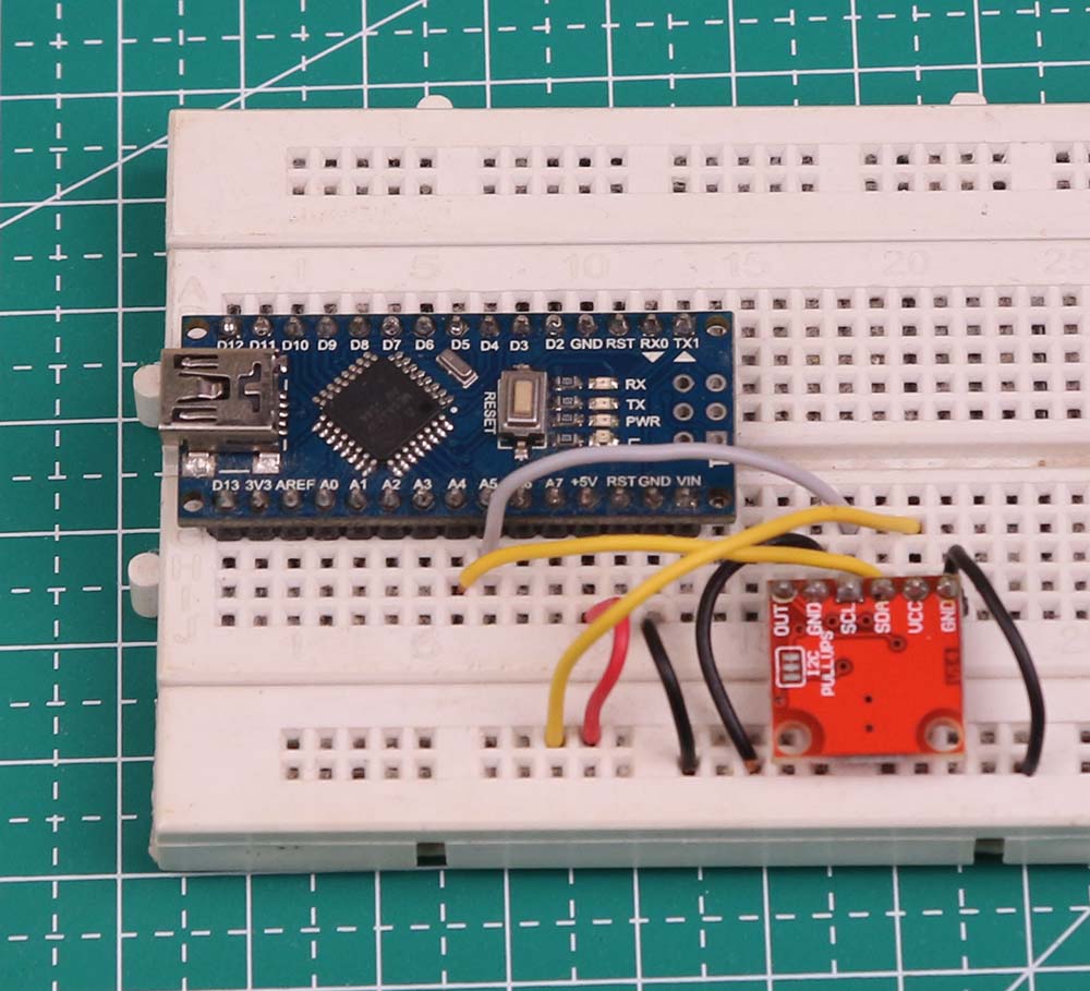

The device will then become ready for use. Power the device with a battery and wait for a few minutes. Now connect the components as shown in the pic below: Fig 4.Connection created in Fritzzing Testing This function will keep updating the GPS data and return the results to the loop function Fig 3 Connection Within the same loop function, a function named get location() will be called. It will check the message for a ‘get location’ command, after which the collected data (with respect to location) will be sent back to the original device. If the message has been received, then convert it into a readable string. Here, we have created a loop function to check whether the incoming message has been received by SIM800L or not. Then we define the pins for GPS module and SIM800L module.Īfter that, we will create the setup function where the baud rate of SIM800L and GPS modules for serial communication are set to 48 respectively.

Next, create some variables that will store the message, GPS location and other data.

In first part of the code, initialise the library in code. To do so, go to tools → click on library manager → search the required library → install the library. Componentsįirst we need to install the libraries ‘Tiny GPS ++’ and ‘FONA’ in Arduino IDE. Input values are not changing: Check the preset connections.First, collect the following components. Try rotating preset and see the effect on the LED and serial monitor. LED brightness is adjusted as per the analog input value. The analog input is printed on the serial monitor. const int analog_ip = A2 //Naming analog input pin const int LED = 3 //Naming LED Pin int inputVal = 0 //Variable to store analog input values void setup ( ) 4. You may download this code (Arduino Sketch) from here. Thus mapping is done by dividing input values by 4. In this example an analog input is taken and it displayed on an LED and the serial monitor.In order to show the input result on LED, Mapping of input value is need. Arduino Nano has 10 bit ADC which means it scales an analog signal in a range of 0-1023. To read an analog signal through Arduino Nano, Analog to Digital conversion is required.

This tutorial teaches how to take analog input using Arduino Nano. This tutorial of Robo India explains the basics of input and output programming in physical computing world.


 0 kommentar(er)
